|
A: This is a very broad
question, and one we get all the time. We'll do the best to
lay it all out for you.
Fuel and Spark, or Fuel Only?
When embarking upon a MegaSquirt installation, you have the
choice of either controlling just your fuel curve or controlling
both spark and fuel. Technically, the ideal tune can only be
found with control over both parameters, provided that the person
doing the tuning knows what they're doing. Often times, the
stock ignition system with stock timing curves can be employed with
a decent amount of success. My recommendation is that if you
choose to control spark as well as fuel, you should a) have a need
to do so, and b) know what you're doing. The only time you
should *need* to play with your stock timing curve is if you
turbocharge your car and the stock ignition timing results in
detonation and/or preignition. Many people turbocharge their
cars with the stock ignition in place (Dodge Neon owners, for
instance) with up to 80% power increase over stock levels while
running the stock ignition timing and adjusting only the fuel curve
with a device such as the MegaSquirt. When in doubt, ask
someone who has had firsthand experience and knows what they're
talking about.
The decision of whether or not to run ignition control with the
MegaSquirt also decides the complexity of your installation.
If you choose to employ a fuel-only solution, you simply need to tap
into just about any signal on the car that pulses once per engine
revolution in order to tell the MegaSquirt how fast the engine is
spinning... exact crankshaft/camshaft position is not needed for
fuel calculations. In this configuration, a MegaSquirt can be
installed on any car in almost exactly the same manner. If you
need to run ignition control, the problem becomes more complex.
Specific modifications to the MegaSquirt itself are often required,
and the MegaSquirt must interface with existing hardware on your
vehicle in a very specific way. We offer MegaSquirts modified
for a few specific ignition configurations. The most complete
reference for MegaSquirtnSpark setup can be found on the
MegaSquirtnSpark Extra Setup page.
Bear in mind that in almost all MegaSquirtnSpark installations, the
MegaSquirt can simply gather RPM and crankshaft position data from
the stock sensors/trigger wheels and leave the ignition in control
of the stock ECU, if so desired. This gives the user the
freedom of controlling spark when they feel up to the task (i.e.
after they've conquered fuel control), without having to re-do a
bunch of wiring.
Spark Control: Interfacing
With Your Stock Ignition
In order for us to be able to set you up with a MegaSquirt that
will control ignition AND fuel, the MegaSquirt needs to get its
tachometer signal from a sensor in the stock ignition system that is
tied to crankshaft or camshaft position. This hardware varies
from car to car. If your car isn't a Neon (420A engine), an
Eclipse (4G63 engine) or a GM engine with a distributor, we don't
know exactly how to connect to it. This is where you'll need
to do some homework in order to use those stock components.
Here are the questions we need answered:
Universal questions:
- How many cylinders does the
engine have?
- Turbocharged, or naturally
aspirated?
Distributor-based ignition
- What type of sensor (or
"trigger") is in the distributor? Is it a VR or a hall
sensor? Engine gurus on online forums dedicated to your car
(there's one for every car, I swear) will know the answer to this
question.
Distributorless ignition
- Do you have a toothed wheel
on the crankshaft that the stock sensor reads from? How many
teeth does it have? All toothed crankshaft wheels have at
least one missing tooth or one inter-tooth gap filled in order to
give the ECU a starting point for maintaining timing. When
you count the teeth on a wheel, take this into account. For
example, on a Ford EDIS car, the wheel is called a "36-1" because
the wheel has 36 teeth (at 10-degree increments), but one is
removed. Consequently, there are actually 35 teeth, but it's
a 36-tooth pattern, so it's referred to as a "36-1" wheel.
Here is a picture from Boost Engineering, a supplier of EDIS
parts.
- Which type of sensor (or
"trigger") reads the toothed wheel? Is it a VR or a hall
sensor? Again, ask an engine guru... he'll know.
- Is your stock ignition
"coil on plug", or "wasted spark"? Coil on Plug (COP)
systems put a small coil on top of each spark plug, so there is no
fat spark plug wire going to a remotely located coil. Wasted
spark systems use a coil pack that is connected to the spark plug
with a traditional spark plug wire.
We can almost always set up
the hardware in the MegaSquirt to work with your stock hardware,
provided that we have accurate and complete answers to these
questions. Without this info, you'll be buying a MegaSquirt
that may or may not work on your engine. Keep in mind that
once you receive your MegaSquirt, you'll need to set up the firmware
with MegaTune so that the timing settings for your stock hardware
are correct. I recommend installing MegaTune (grab the latest
version in
this location) and playing with settings before actually setting
up the MS on the car.
EFI Conversion: Which Parts
Do I Need?
There is a collection of parts that are common to every
speed-density EFI system that the system must have in place in order
to operate. These parts can be purchased from us, found in a
junkyard, taken from a donor vehicle, etc.
- ECU (MegaSquirt, in this
case)
- Fuel injectors and injector
rails
- Fuel pressure regulator
- High-pressure fuel feed and
return lines
- Intake manifold suitable
for fuel injector mounting, or a TBI system
- Throttle position sensor
(or wide-open-throttle switch)
- High-pressure electric fuel
pump designed for EFI duty
- Exhaust Gas Oxygen (EGO)
sensor
- Intake air temperature and
coolant temperature sensors
- Manifold Absolute Pressure
(MAP) sensor (internal to the MegaSquirt)
- Wiring to tie it all
together
- Ignition system (either a
distributor or the hardware necessary for a distributorless setup)
How Do I Wire It Up?
The installation procedure for a MegaSquirt varies on every
vehicle to some degree. The procedure depends on a few key
questions you'd need to answer for yourself:
1) Do you want to put your stock EFI system to work for you?
If the stock ECU and wiring are left in place, installation is
fairly simple. Stock injector wires can be used, many sensor
wires can be tapped (sensors will be covered in detail later), and
the stock power wiring can be used. For instance, you don't
even need to run your TPS power and ground wires, you simply need to
tap into the center wire of your stock throttle position sensor with
the TPS SIG wire. The same logic applies to the stock
narrow-band O2 sensor. The stock ECU can often control the
fuel pump and idle air control functions for you as well.
Lastly, the stock main power relay can be used, with the MegaSquirt
running from the "on while key on AND during cranking" power wire.
As for fuel injectors, all you need to do is disconnect the fuel
injector switched ground leads (not the common +12V leads, which can
be left in place) and connect them to the outputs of the MegaSquirt.
The same logic applies to the ignition coil(s), once the proper
wiring and modifications are in place for ignition control.
New temperature sensors usually need to be wired separately, which
will be explained later. For this type of installation, a
Relay and Power Distribution Board isn't really necessary, since all
of the features it provides are already built into your stock
wiring. Save yourself some money and do without it, unless you
want to totally isolate your MegaSquirt wiring from the stock
system.
2) Converting from a carburetor, or just want to ditch your stock
wiring and ECU entirely?
If you'll be starting from scratch with your EFI
system for one reason or another, you'll need to do a bit more
wiring and buy a few more system components. We advise you to
carefully consider all ramifications of removing the stock ECU from
your car without a good reason... for instance, a Neon's ECU feeds
the crankshaft position sensor (a necessary component) a 9V supply
voltage, which would require additional circuitry to run without the
stock ECU. Alright... back to the wiring. What you'll
probably want to do is get a Relay and Power Distribution Board.
This board offers fuses, relays, and a central wiring hub that
you'll likely find either useful or essential in your installation.
We offer this board for sale, as well as a range of cable kits with
which to connect the Relay and Power Distribution Board to the
MegaSquirt. Once you have your MegaSquirt and Relay and Power
Distribution Board installed in the car, wiring the system is fairly
simple. Each output terminal of the Relay and Power
Distribution Board is labeled with its function, and these labels
correspond to the labels stamped on the wires in our harness kit.
It makes installation a breeze, relatively speaking of course.
3) Do you know exactly how your stock temperature sensors are
controlled by the stock ECU?
If you want to use your stock intake air temp and
coolant temp sensors, you have to do one of two things: a) know
exactly how they're driven by the stock ECU, or b) remove the stock
ECU from the picture entirely. The problem is essentially
this: The stock computer puts a fixed-value resistor in series with
a temperature sensor, and then drives the series circuit with a
supply voltage. The voltage is balanced between the sensor (a
thermistor, or thermally varying resistor) and that resistor (often
called the 'bias resistor'), and that balance is measured in order
to calculate temperature. Knowing that resistor value, one
could simply tap into the stock sensor signal. There are
instructions here for doing so in
this archived YahooGroup message. If you don't know how to
tap your stock temperature sensor signals, we recommend purchasing
and installing new GM temperature sensors (which we offer), and
running the wiring independently of the stock sensor.
|
|
A: Although our harness
kits now come with terminals pre-attached, which should make this
process unnecessary, we've left this information on the site for
those who happen to run into a situation where wires need to be
attached to a D-sub connector.
First off, here are the basics:
a) Make sure you're not using your huge soldering gun (for pipes,
etc.) to do the job. A $7 Radio Shack 25W soldering iron is
perfect. Ideally, a temperature-controlled soldering station
can be used, but if you already had one of those, you'd probably
already know how to solder the connector... I built my
MegaSquirt and my harness with a $7 iron.
b) Heat the part with the soldering iron and then touch the *part*
with the solder. This is to ensure that the flux is flowing across
the part instead of burning up on the iron. The flux cleans the
surface and helps the solder to flow across it, so if you burn the
flux up before it hits the part, the solder might not flow and the
joint could be 'cold' and may develop into an open circuit at some
point.
Now for some photos... (click on a photo to see larger version)
(Note: Don't solder the sensor return wires to the pins that
I did if you're running a relay board... this harness doesn't use
one. With a relay board, there should be a main ground wire in
the center, and a sensor return wire on pin 19.)

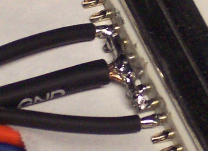
Soldered ground wires |
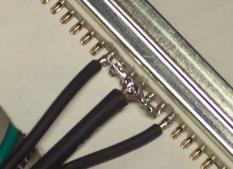
More soldered ground wires |

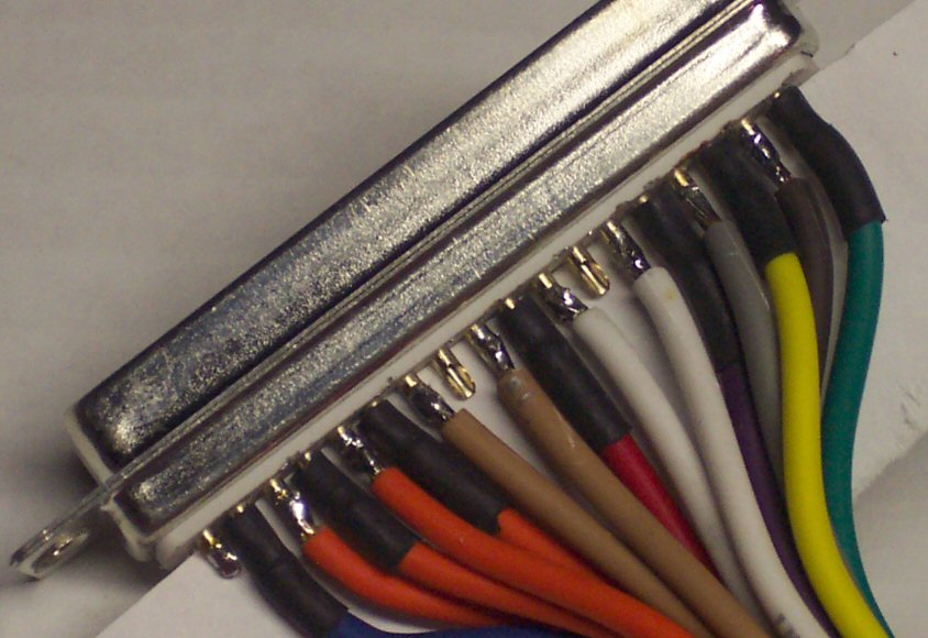
Soldered signal/power wires |

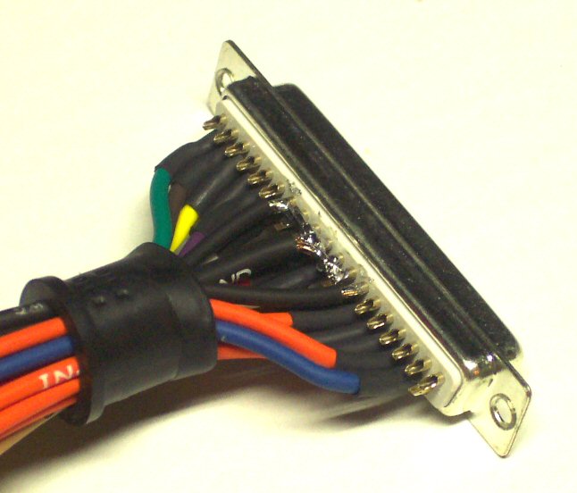
Completed connector
(somewhat redundant heat shrink, perhaps) |
Here's the process:
1) Lightly tin (coat with solder) the pins on the connector. This
shouldn't take too much heat. Add enough solder that the 'cup' shape
in the pin is full to the point of being almost leveled off with
solder. This will serve as a sort of reservoir when the wire is
soldered on.
2) Using needlenose pliers, make sure the strands of the stripped
wire are nicely packed together. Cut and re-strip to about 1/16-1/8"
if the strands are too bent to be completely straightened.
3) Completely tin the stripped portion of the wire. I found it
easiest to hold the wire down with something (a vise, a book on a
table, etc.), apply heat to the very *tip* of the wire, and touch
the solder to the *side* of the stripped portion of the wire. The
solder will very easily 'wick' into the wire. Make sure all sides of
the stripped wire are tinned, but don't put so much solder on there
that it balls up on the wire. If it does, get it hot and quickly
shake the excess solder off of the wire.
4) Hold the connector in some kind of vise. Grab the edge of the
connector with a pair of Visegrips if you don't have a vise, and
just set it on the table. The Visegrips will keep the connector from
moving around too much while you're using your other two hands to do
the soldering.
5) Lay the tip of the wire onto the top of the solder cup (don't
worry if it doesn't fit *into* the solder cup, it's too big), and
apply heat with the soldering iron to the side of the stripped wire.
The iron will melt the solder in the wire, and that will in turn
melt the solder in the connector pin. The excess solder in the
connector pin will supply all that is needed for the connection, so
no solder needs to be added. As soon as the solder has completely
flowed between the wire and the pin, remove the heat while still
holding the wire in place for a second or so. The solder will freeze
up, and you'll have a good solder joint.
Note: Be sure to keep the
joint small (i.e. don't add too much solder or smash the tip of the
wire outward while soldering), and there should be very little risk
of shorts between the pins. If you want to be really sure, you
can use 3/16" heat shrink tubing on every *other* pin to prevent
shorts between adjacent pins. Just be sure to remember to
slide the tubing over the wire before you solder it! Carefully
applying heat with a lighter or a match will work just fine on the
heat shrink tubing, if you don't own a heat gun. |